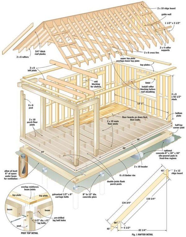
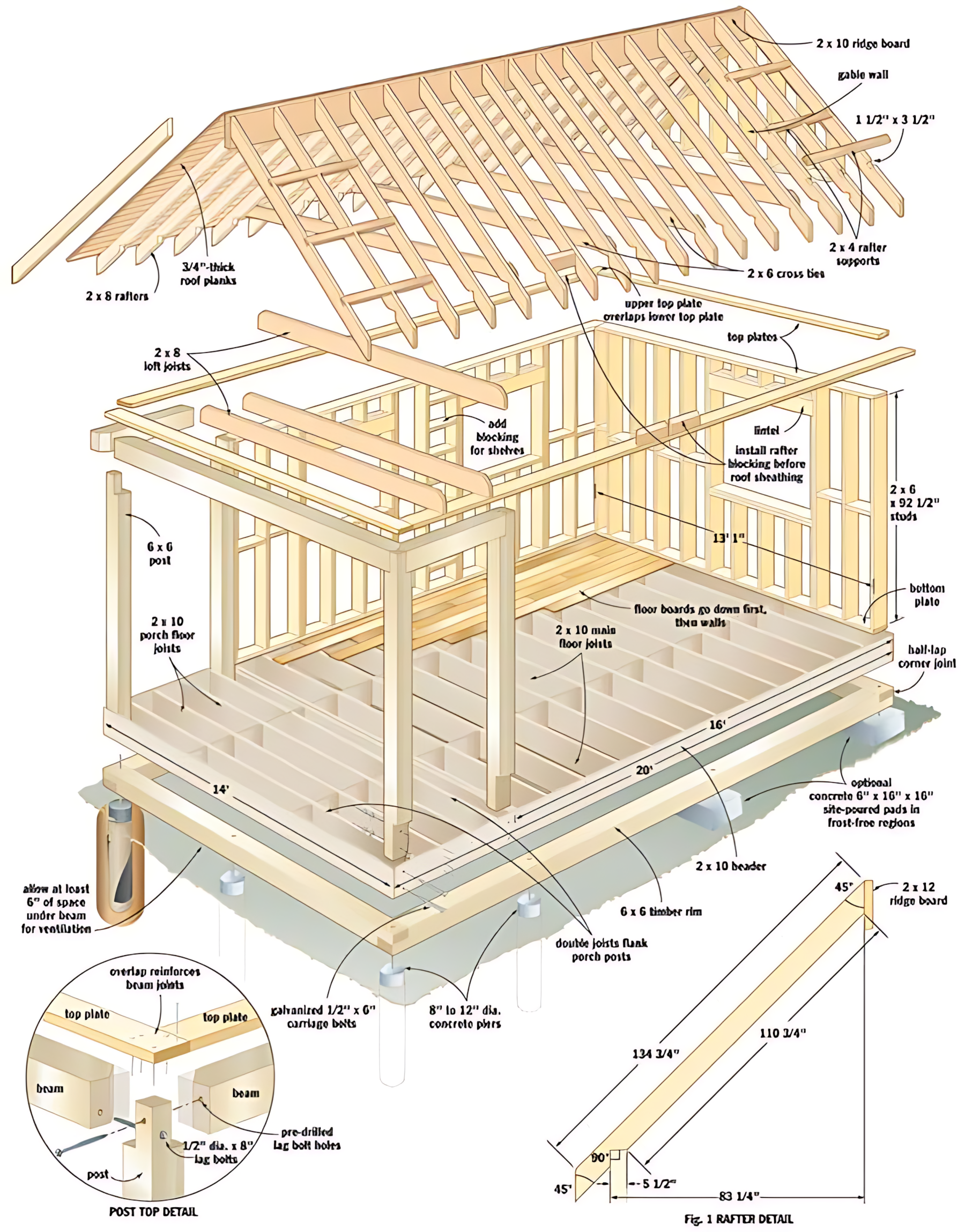
Local builder transforms bare ground into a sturdy post-and-beam shell using off-the-shelf lumber, concrete piers and simple joinery—no heavy machinery required.
1. Breaking Ground and Setting the Stage
At dawn, the foundation team arrived to mark out a 20-by-16-foot rectangle on level soil. Stakes and twine defined the footprint; string lines ensured perfect squareness at each 90° corner. A soils inspector confirmed adequate bearing capacity, then holes were augered 8–12 inches in diameter, 30 inches deep, spaced to support critical load points beneath future porch posts and the main floor.
2. Pouring Piers and Placing Embedded Hardware
Into each augered hole, concrete was poured to form piers rising just above grade. Before the concrete set, galvanized ½-inch by 6-inch carriage bolts were positioned vertically—these would later fasten the floor rim and beams. Careful leveling of each pier top ensured a uniform 6 inches of crawl-space clearance beneath the future floor joists.
3. Laying the Timber Rim and Porch Beams
With piers cured, 2×10 pressure-treated rim joists were laid and bolted down to the embedded carriage bolts, forming a continuous border around the future floor. At the front edge, a pair of 6×6 porch posts were erected on doubled-joist beams (“double joists flank porch posts”) and temporarily braced—this would carry the porch roof load. Each 6×6 post top was notched to accept beams and secured with pre-drilled ½-inch × 8-inch lag bolts, per the “post-top detail” inset.
4. Installing Main Floor Joists
Between the rim joists, 2×10 floor joists were set at 16-inch centers, spanning 14 feet from back to front. Joists were hung using joist hangers where they met rim boards and flush-nailed into the band joists at the rear. Care was taken to run “floor boards go down first, then walls,” meaning the subfloor would later be laid before standing the walls. Blocking was installed between joists at mid-span for stiffness.
5. Sheathing the Subfloor and Preparing for Walls
Tongue-and-groove subfloor planks were laid atop the joists, staggered end-to-end for strength, and fastened with ring-shank nails. The seamless surface was swept clean and pre-drilled holes aligned over the embedded bolts for final tightening of the rim to the piers.
6. Raising the Wall Plates and Studs
Next, 2×6 bottom plates and matching top plates—92½ inches long—were prepared. Upper plates overlapped lower plates at corners to tie perpendicular walls together. Studs (also 2×6) were cut to length and stood every 16 inches, toe-nailed into the bottom plate, then knee-braced and nailed to the top plate. Openings for windows and doors received doubled studs (jack and king studs) and headers.
7. Adding Loft Joists and Blocking
Inside the cabin, 2×8 loft joists were installed atop the walls, running laterally to create a future sleeping loft. These were set on ledger boards attached to the studs and nailed in place. In between, blocking was fitted to reinforce the assembly and provide shelf support. Proper alignment guaranteed the ceiling would be flat and strong.
8. Preparing for the Roof: Ridge Board and Rafter Layout
A pair of 2×10 ridge boards—measuring 134¼ inches along the hip and 110¾ inches along the main run—were pre-cut to the exact 45° miter at each end, per the “rafter detail” diagram. The builder marked each rafter, transferring the plumb cut and seat cut from the template to 2×8 rafter stock.
9. Installing Rafter Supports and Cross Ties
On top of each gable wall, 2×10 ridge board was secured temporarily with braces. Then, common rafters (2×8) were installed at 24-inch centers, their lower ends resting on the top plate and upper ends butting into the ridge board. Each rafter was fastened with toenails and metal connectors. Mid-span cross ties (2×6) were nailed between opposing rafters to prevent spreading.
10. Sheathing the Roof
Once rafters were all in place, ¾-inch tongue-and-groove roof planks were laid directly over them, running from eave to ridge without break. The boards were fastened with ring-shank nails, yielding a rigid diaphragm that will later carry roofing underlayment and shingles. Overhangs were cut to length for proper drip edge.
11. Reinforcing Key Connections
Attention to detail shines in the “post top detail” close-up: beams were not only lag-bolted but also reinforced by overlapping the upper top plate over the lower, creating a sandwich effect that ties posts, beams and plates into a single load-path. All lumber ends and edges were sealed with preservative to guard against moisture.
12. Wrapping Up and Weatherproofing
With the structure framed, the crew applied house-wrap over the exterior studs before flashing window and door openings. Roof sheathing received felt underlayment and drip edge. Windows and doors will follow, and the porch roof (a smaller hip roof) will mirror the main roof pitch, delivering cohesive shelter.
Builder’s Note:
All framing was done with readily available 2× lumber and simple hardware—no cranes or heavy gear. Total build time: under one week for a two-person crew. Ventilation beneath the floor prevents moisture issues; blocking ensures rigidity; overlap detailing at plates and posts guarantees that wind and snow loads are safely carried to the foundation.
This accessible approach can be replicated by any committed DIYer or small contractor aiming for a robust, code-compliant timber frame.