1. Laying Out the Grid
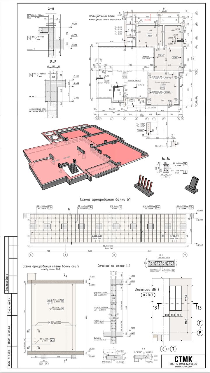
At first light, surveyors stake out the slab boundary per the form-plan dimensions. Using batter-boards and taut strings, they mark the exact grid lines—axes 1 through 9 and A through E—so every wall, column and beam will fall perfectly in place. Precision here means the difference between a square slab and costly rework later.
2. Excavation and Subbase Preparation
Excavators remove the topsoil to the required depth, exposing undisturbed subgrade. Crews then spread and compact a 100 mm gravel subbase, ensuring uniform bearing. Any soft spots are flagged, under-pinned or replaced. A clean, level subgrade sets the stage for uniform concrete thickness and crack-free performance.
3. Placing the Perimeter and Internal Formwork
Carpenters assemble robust timber formwork along the slab’s edge—built to the plan’s 0.200 m (top of slab) and 0.850 m (bottom of beam) elevations. Along the grid’s interior, they install shuttering for ribs, drop-pan beams B1 (detailed in the “Схема армирования балки B1”) and column pockets. All form faces are braced and checked for level: each line and corner is re-measured to the original layout.
4. Installing Horizontal & Vertical Reinforcement
With forms in place, ironworkers begin the steel cage. In the beam B1, 12 mm Ø bars at L=2990 mm and 16 mm Ø bars at L=2650 mm are laid along the beam’s length, tied with 8 mm stirrups at 200 mm centers (see detail 6-6). Wall cages along axis 5 receive vertical bars L=1550 mm at 200 mm spacing, cross-tied with horizontal reinforcement to ensure uniform stiffness. All rebar is supported on plastic chairs to maintain the specified 40 mm cover.
5. Shear-and-Punch-Down Checks
Prior to placing mesh, engineers walk the grid checking cover, bar sizes and lap lengths. The drawing calls for 3 × L=1900 mm bars at critical sections (sections A-A and B-B), each overlapping by 300 mm for a total development length. Any misplaced bar is retied or shimmed until every connection matches the reinforcement schedule exactly.
6. Laying Out the Slab Mesh
Over the compacted subbase, workers roll out ½″-Ø welded-wire mesh at 200 mm centers, cutting to the slab plan’s full footprint. Mesh sheets overlap by at least one full grid spacing and are tied together so that the slab acts monolithically. Chairs lift the mesh 70 mm off the gravel, centering it within the 100 mm slab thickness.
7. Embedding Service Conduits and Inserts
Next, plumbing and electrical sleeves—PVC pipes for under-slab services—are laid where walls and partitions will rise. Roof-drain plates and anchor inserts for future columns are blocked out, per the plan’s callouts (e.g., mark “Лестница ЛВ-2” at 0.22 m³). All penetrations are checked against the formwork plan to avoid last-minute adjustments.
8. Final Formwork Inspection
The site engineer conducts a “pre-pour walk,” verifying:
- Form dimensions and elevations to within ±5 mm
- Rebar cover and lap lengths per “Схема армирования” details
- Proper support for mesh, beams and embedded inserts
Any non-conformance triggers an immediate fix; only a fully signed-off formwork gets the green light for concrete.
9. The Big Pour
Ready at midday, two concrete pumps roar to life. The first wave fills beam shuttering, carefully compacted with pokers to eliminate air pockets. Immediately after, the slab zone is flooded. Teams spread and level the concrete in stages, screeding along straightedges to strike off at the 0.200 m top elevation. As the slab self-levels, workers follow behind with darbies and bull floats, smoothing the surface and exposing aggregate where specified.
10. Curing and Striking Forms
Within hours, curing blankets are laid and periodic misting begins, guarding against rapid moisture loss. Formwork for beams and columns remains in place for 72 hours, then is stripped and the concrete allowed to reach design strength. Slab edges are chamfered, and control joints—laid out per the slab plan—are cut to guide cracking along predetermined lines.
Wrap-Up:
In under a week, a skeletal grid on paper transforms into a solid slab-and-beam foundation ready to support walls, columns and floors above. Rigorous layout, exacting formwork and disciplined reinforcement placement—backed by staged inspections—ensure the finished concrete will perform exactly as engineered, bearing loads and resisting cracks for decades.