A comprehensive, step-by-step guide to diagnosing and correcting design and installation mistakes— from PV array sizing and controller configuration to heat‐pump integration and backup heater bypass—ensuring your grid‐tied and off‐grid loops reliably deliver sustainable hot water.
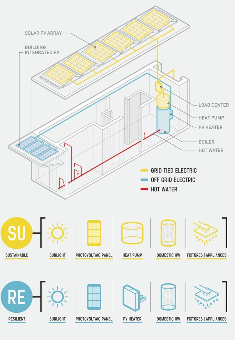
As homeowners increasingly turn to renewable energy, integrated solar photovoltaic (PV) hot water systems—combining rooftop PV arrays, heat pumps, and PV electric immersion heaters—promise year‐round, low‐carbon domestic hot water. Yet even minor missteps in design or installation can leave panels under-utilized, heat pumps cycling ineffectively, and backup elements idle when they’re needed most. In this 1,000-word, seven-phase guide, we’ll diagnose the four most common mistakes shown in the schematic above—mismatched PV sizing, missing diversion controller, lack of backup heater bypass, and uncoupled grid tie vs. off-grid loops—and walk you through precise corrections to optimize efficiency, reliability, and resilience.
Phase 1: Verify and Right-Size Your PV Array
Mistake #1: Undersized PV Array Relative to Heat Pump and PV Heater Loads
A PV array that can only meet 50 percent of your system’s summer-day demand forces reliance on grid power or gas, undermining sustainability goals.
- Calculate Year-Round Hot Water Demand:
- Gather historic daily hot water usage (liters/day) from utility bills or an inline flow meter.
- Convert to energy: 4.2 kJ rises 1 kg of water by 1 °C. For 200 L/day from 15 °C to 55 °C:
Q=200 kg×40 K×4.2 kJ/kg\cdotpK=33,600 kJ=9.33 kWh/day.Q = 200\text{ kg} \times 40\text{ K} \times 4.2\text{ kJ/kg·K} = 33{,}600\text{ kJ} = 9.33\text{ kWh/day}.
- Assess PV Insolation:
- Use your locale’s average peak sun hours (e.g., 4 h/day in winter, 6 h/day in summer).
- For 9.33 kWh demand at 5 h average:
Parray=9.335 h=1.87 kW.P_\text{array} = \frac{9.33}{5\text{ h}} = 1.87\text{ kW}.
- Add 20 percent to cover wiring and controller losses: 1.87×1.2 ≈ 2.25 kW.
- Select and Mount Modules:
- Choose modules whose Voc and Isc match your load-center inputs (e.g., six 375 W panels in a 2 × 3 series/parallel configuration yields 2.25 kW).
- Tilt and azimuth: set tilt to latitude ±10° and true‐south orientation for maximal year-round yield.
Phase 2: Install and Configure a Dedicated Hot-Water Diversion Controller
Mistake #2: Driving the Heat Pump Directly from a Standard Inverter—No Peak-Shaving or Diversion Logic
Without a diversion controller, surplus PV can’t be routed to the PV heater element, and the inverter may idle excess power back to the grid.
- Choose a Hot-Water Solar Controller:
- Look for a unit with MPPT input, dual‐relay outputs (heat-pump and immersion heater control), and communication to your PV inverter.
- Ensure it supports differential temperature setpoints (e.g., activate the heat pump when panel voltage > 80 V DC).
- Wiring the Controller:
- Connect PV array output to the controller’s MPPT terminals.
- Run the controller’s dedicated relay output to the PV immersion heater via a suitably rated contactor (e.g., 240 VAC, 20 A).
- Program enable thresholds: differential setpoint of +10 °C between panel temperature and tank top sensor.
- Configure Priority Logic:
- Primary: power the heat pump while PV input > pump minimum DC voltage (e.g., > 48 V).
- Secondary: once the tank is within 5 °C of setpoint, divert remaining PV power to the immersion heater.
Phase 3: Integrate the Heat Pump for Maximum COP
Mistake #3: Installing the Heat Pump with No Bypass or Buffer, Causing Short Cycling
A directly‐coupled heat pump without thermal storage or bypass sees rapid temperature swings—lowering coefficient of performance (COP) and reducing unit life.
- Add a Thermally Stratified Buffer Tank:
- A 200–300 L stainless steel or coated buffer tank dampens inlet/outlet temperature swings.
- Mount the heat pump’s primary flow into the tank’s mid-height port to allow stratification: cold return enters bottom; heated flow leaves top.
- Install a Bypass Valve:
- When water temperature at tank top exceeds 55 °C, the controller should open a three-way diverter valve.
- This shunts compressor discharge water directly to the tank, avoiding rapid on/off cycling.
- Flow and Head Calculations:
- Ensure pump delivers the heat pump’s nominal flow (e.g., 25 L/min).
- Size piping to ¾–1″ PEX or copper to keep pressure drop < 0.5 bar; install balancing valves and a flow meter on the primary loop.
Phase 4: Separate Grid-Tied and Off-Grid Electric Loops
Mistake #4: Mixing Domestic Loads on the Heat-Pump Loop, Causing Grid Draw During Clouds
If the controller shares the load center with other off-grid circuits (lighting, outlets), transient cloud cover can deplete the battery or force grid draw.
- Define Two Electrical Buses:
- Grid-Tied Bus: PV inverter feeds household loads (lighting, appliances) and exports surplus to the grid.
- Dedicated Hot-Water Bus: Powered by MPPT diversion controller only, isolated from the house loads.
- Install a Transfer Switch or Relay:
- This auto-switches the PV-heater load to grid power only if PV generation drops below a threshold (e.g., 500 W).
- Prevents battery or grid-tie fluctuation from impacting water-heating loops.
- Ground and Surge Protection:
- Provide separate surge arrestors on each bus and ensure proper equipment grounding for both heat-pump and grid-tied inverters.
Phase 5: Ensure Redundant Backup Heating
Mistake #5: No Manual or Automatic Heat Source for Extended Low-Sun Periods
A fully PV-dependent system can leave users without hot water during prolonged overcast or maintenance.
- Add a Gas or Electric Backup Element:
- In cases of extended clouds, a gas burner or a second AC‐powered electric heating element can maintain temperature.
- Wire it separately, controlled by a high-limit thermostat at 45 °C to auto-activate when solar heating isn’t sufficient.
- Integrate into Control Logic:
- Program the solar controller to monitor both PV-diverted and grid-tied loops.
- If neither can raise tank water above 40 °C within a set time (e.g., 2 hours), engage the backup.
- Safety and Compliance:
- Install all gas or high-wattage elements per local code: pressure relief valves, venting, and proper overcurrent protection.
Phase 6: Commissioning and Performance Tuning
- Verify Temperatures and Flow Rates:
- With data loggers on the PV array, heat-pump inlet/outlet, and tank, run a full sunny-day test.
- Expect a solar fraction (solar-supplied energy/total energy used) above 60 percent.
- Monitor COP of the Heat Pump:
- Calculate COP = Heat delivered (kWh) ÷ Electricity consumed (kWh).
- Aim for COP > 3.5 under nominal conditions.
- Test Diversion Thresholds:
- Shade panels to ramp down PV output—confirm automatic switch to immersion heater then to backup source.
Phase 7: Ongoing Maintenance and Seasonal Adjustments
- Panel Cleaning and Inspection:
- Wash modules monthly with deionized water and soft brush—dirty panels lose 10–20 percent efficiency.
- Controller Firmware Updates:
- Check the manufacturer’s site quarterly; new releases often improve MPPT algorithms and diverter logic.
- Heat Pump Servicing:
- Annually inspect refrigerant charge, coil cleanliness, and bearing lubrication; improper maintenance can halve COP.
- System Log Reviews:
- Every season, analyze data logs for reduced solar fraction or heater runtime. Seasonal adjustments (tilt angle, controller thresholds) can recover 10–15 percent performance.
Conclusion
By systematically addressing PV sizing, adding a dedicated diversion controller, coupling the heat pump with a buffer and bypass, separating electrical loops, ensuring backup heating, and committing to rigorous commissioning and maintenance, you’ll correct the most common pitfalls in integrated solar PV–driven hot water systems. The result is a truly resilient, energy-efficient solution—delivering high temperatures even in variable weather, reducing reliance on fossil fuels, and extending equipment life for decades of sustainable domestic hot water.