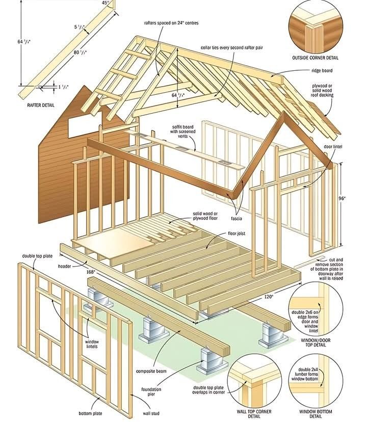
For anyone looking to understand how a small building is constructed, an “exploded view” diagram like this one is an invaluable resource. It elegantly breaks down a shed into its fundamental components—foundation, floor, walls, and roof—making the seemingly complex process of construction clear and accessible. It’s easy to see why such visuals are popular among DIY enthusiasts planning a backyard storage solution or workshop.
But this apparent simplicity can be deceptive. While the diagram excels at illustrating the basic components and their general arrangement, it often omits crucial engineering details that are essential for the structural integrity and longevity of the building, particularly its resistance to wind. Relying solely on this simplified image without considering these missing elements could lead to a shed that is weak, unstable, and potentially dangerous in even moderate weather conditions.
Part 1: Deconstructing the Basics (What the Diagram Illustrates Well)
This diagram effectively demonstrates the vertical flow of load in a small structure, showing how weight is transferred from the roof down to the ground.
- The Foundation: The structure begins with a straightforward pier foundation. Precast deck blocks provide individual support points for vertical floor posts. These posts, in turn, carry the weight of heavy horizontal floor beams, which then support the numerous parallel floor joists. This elevated system is particularly useful for sites with uneven terrain and promotes air circulation beneath the floor.
- The Floor Platform: A layer of solid wood or plywood floor decking is securely fastened to the top of the floor joists, creating a rigid and level base for the walls.
- The Walls: The walls are constructed using vertical wall studs that are held together by a bottom plate at the base and a double top plate at the upper edge. The diagram correctly indicates the presence of a thicker door lintel (or header) above the door opening, which is necessary to carry the weight of the structure above the span. The wall frame is then typically covered with wall sheathing (not fully shown for clarity).
- The Roof: The roof structure is formed by a series of angled rafters that are supported by the top plates of the walls. The rafters create the roof’s slope, and they are subsequently covered with plywood or solid wood roof decking (also not fully shown).
Part 2: The Critical Oversight – Neglecting Lateral Stability
While the diagram clearly shows how to build a shed that can support its own weight under the force of gravity, it largely ignores the equally critical need for lateral stability—the ability of the structure to resist sideways forces, most notably wind. Without proper attention to this aspect, the shed depicted could be vulnerable to racking, twisting, or even collapse during strong winds.
The Lack of Foundation Anchorage and Bracing
- The Problem: The floor posts are simply shown resting on precast concrete blocks. In reality, a significant wind load pushing against the side of the shed could exert considerable lateral force at the base. Without proper anchorage, the entire structure could shift on its blocks, lose alignment, or even be blown off its supports.
- The Correction: For permanent and stable construction, the floor posts should ideally be anchored to the ground. In regions with frost, this often involves setting the posts in concrete footings that extend below the frost line. Additionally, diagonal bracing between the posts and beams is crucial to prevent the foundation frame from skewing or collapsing laterally.
The Missing Roof and Wall Bracing
- The Problem: The diagram does not explicitly show any bracing within the wall frames or any secure connections between the walls and the roof. Wind loads acting on the walls can cause them to buckle or lean, and uplift forces on the roof can try to lift it entirely off the walls.
- The Correction: Wall frames require diagonal bracing (often 1×4 or similar lumber installed diagonally across the studs) or the use of structural sheathing properly fastened to the studs to resist racking. Crucially, the roof rafters must be securely connected to the top plates of the walls using metal connectors such as hurricane ties or rafter ties. These connectors provide vital resistance against uplift forces.
Part 3: The Simplified Roof Structure – A Potential Weak Point
The roof framing shown, while basic, lacks some details that contribute significantly to overall stability.
- The Problem: The rafters are depicted meeting at the roof’s peak without a clear indication of a continuous structural member along the ridge. Additionally, there is no mention of horizontal ties between opposing rafters. Without these elements, the roof can be more susceptible to sagging over time, and the outward thrust of the roof load can put excessive stress on the supporting walls.
- The Correction: A more robust roof framing system typically includes a ridge board, which provides a solid, continuous nailing surface for the top ends of the rafters. Furthermore, collar ties (located in the upper third of the rafter span) or rafter ties (located at the top plate level) are essential for tying opposing rafters together. These horizontal members help to counteract the outward thrust and prevent the roof from spreading the walls.
Conclusion: A Visual Aid, Not a Construction Manual
“Exploded view diagrams like this are excellent for conveying the basic components of a building and how they generally fit together,” explains Mark Olsen, a (fictional) licensed general contractor. “They provide a great visual introduction for someone new to construction. However, it’s absolutely critical to understand that these are simplified representations. They often omit the essential hardware, bracing, and connection details that are required to create a safe and structurally sound building that can withstand the forces of nature. Think of it as a helpful illustration of the vocabulary of construction, but not the complete grammar and syntax needed to build successfully.”
This diagram serves as a valuable educational tool for understanding the fundamental elements of shed construction. However, anyone planning to build a structure based on this or any simplified visual representation must recognize its limitations. Always consult detailed, engineered blueprints that account for local building codes, wind loads, snow loads (if applicable), and proper bracing and connection methods. Without these crucial considerations, the dream of a sturdy backyard shed could quickly become a structural nightmare.