For anyone looking to understand how a house is built, an “exploded view” diagram like this one is an incredible tool. It elegantly separates a shed into its core components—foundation, floor, walls, and roof—making the complex process of construction seem logical and straightforward. It’s easy to see why such images are popular among DIYers planning a backyard project.
But this simplicity is deceptive. The diagram, while excellent for showing the basic parts, omits the critical engineering details that hold everything together against real-world forces like wind. Building a shed based on this simplified image alone, without understanding what’s missing, could lead to a structure that is weak, unstable, and could even collapse in a strong storm.
Part 1: Assembling the Pieces (What the Diagram Shows Well)
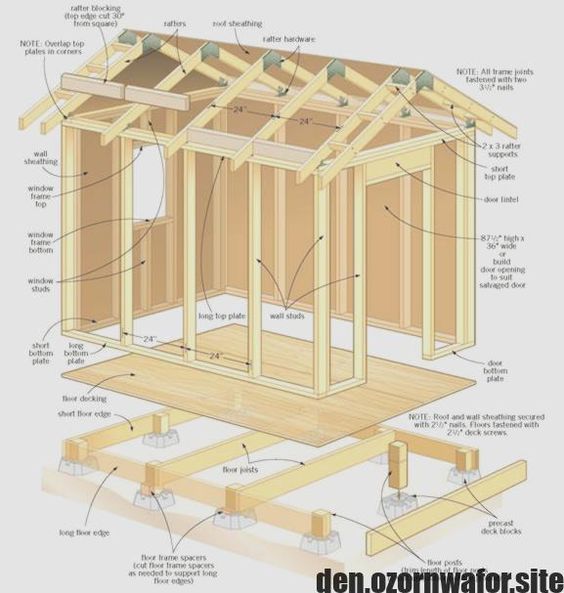
This diagram is a fantastic educational guide to the vertical “load path” of a building—how the weight of the structure is transferred down to the ground.
- The Foundation: The entire structure begins with a simple pier foundation. Precast deck blocks provide a base for the vertical floor posts. These posts support heavy beams, which in turn hold up the floor joists. This elevated system is great for uneven ground and provides airflow under the floor.
- The Floor Platform: A layer of floor decking (plywood or OSB) is fastened to the joists, creating a solid, flat platform to build on.
- The Walls: The walls are assembled from vertical wall studs sandwiched between a base bottom plate and a short top plate. The diagram correctly shows a thicker door lintel (header) to span the wide door opening and carry the roof’s weight above it. The entire frame is then covered in wall sheathing.
- The Roof: The roof is framed with individual, angled rafters that sit on the walls. These are then covered with roof sheathing to create the final roof surface.
Part 2: The Critical Mistake – A Structure with No Bracing
The diagram does an excellent job of showing how to build a shed that won’t collapse under its own weight (gravity). But it almost completely ignores the second, equally powerful force that every building must resist: lateral load, or the sideways force from wind.
Without proper bracing, this shed is like a house of cards—strong vertically, but dangerously weak horizontally.
The Missing Foundation Bracing
- The Problem: The diagram shows the floor posts simply resting on the precast deck blocks. A strong, sustained wind pushing on the large side of the shed could cause the entire structure to sway, “rack” (lean out of square), or even slide right off its foundation blocks.
- The Correction: The foundation must be braced against this sideways movement. This is typically done by installing diagonal 2×4 braces in an ‘X’ pattern between the posts and beams. For a truly robust and permanent structure, the posts should be sunk into concrete footings that extend below ground, anchoring the entire building to the earth.
The Missing Roof-to-Wall Connection
- The Problem: The rafters are shown simply resting on top of the walls. A strong wind can create immense uplift forces, acting like a giant wing and trying to rip the roof off the building.
- The Correction: Modern building codes in virtually all parts of the US and EU require metal connectors (like hurricane ties or seismic anchors) to create a continuous, strong connection from the rafters down to the wall studs.
[Image showing hurricane ties connecting roof rafters to a wall’s top plate]
Part 3: The Unstable Roof (The Second Hidden Flaw)
The simplified diagram also omits two essential components of a conventionally framed roof.
- The Problem: The rafters are shown meeting at a sharp peak with nothing in between. Without a structural member at the ridge and horizontal ties across the span, the downward force of the roof would constantly push outwards on the walls, causing them to bow and eventually fail.
- The Correction: A traditionally “stick-built” roof requires a ridge board—a horizontal board that runs along the peak and provides a solid nailing surface for the top of the rafters. It also requires collar ties or rafter ties—horizontal boards that connect opposing pairs of rafters, forming a stable triangle and preventing the walls from being pushed apart.
Conclusion: A Diagram Is Not a Blueprint
“Exploded diagrams are fantastic for showing the basic vocabulary of a building—the ‘nouns’ like joists, studs, and rafters,” says Dr. Anya Sharma, a (fictional) civil engineer specializing in residential structures. “But they often leave out the critical ‘verbs’—the bracing, the connections, the metal hardware—that tie everything into a single, resilient system. A building that can’t handle wind is an unsafe building. These visuals are for conceptual understanding only; they are not a substitute for a complete, engineered, and code-compliant building plan.”
This diagram is an invaluable learning tool. It provides a clear, intuitive look inside a building’s anatomy. But before you start building, it is essential to seek out a full set of construction blueprints that include the critical details for bracing and connections required in your specific area. Understanding how to build a structure that can withstand not just gravity, but also the wind, is the key to creating a project that is safe, strong, and will last for decades.